Modified Hopkinson Pressure Bar for Studying Dynamic Fracture Toughness
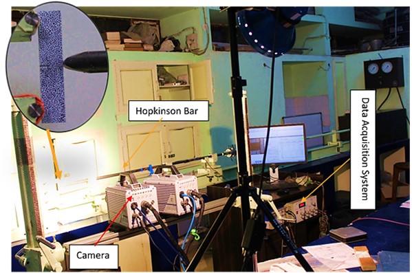
Schematic of the modified Hopkinson pressure bar (MHPB). In recent time it has emerged as most common apparatus to determine the dynamic fracture toughness under high strain loading for three-point bend specimens. It consists of several components such as storage cylinder, barrel, high strength steel bars, projectile, and a 3-point bend fixture. A pulse shaper is placed between the projectile and incident bar to provide a more suitable incident pulse and thereby reducing three-dimensional effect. The axial strain was recorded at the two locations on the incident bar using the strain gauges.
Split Hopkinson Pressure Bars SHPB (Split Hopkinson Pressure Bars) for high strain rate evaluation under dynamic compression and tensile loads:
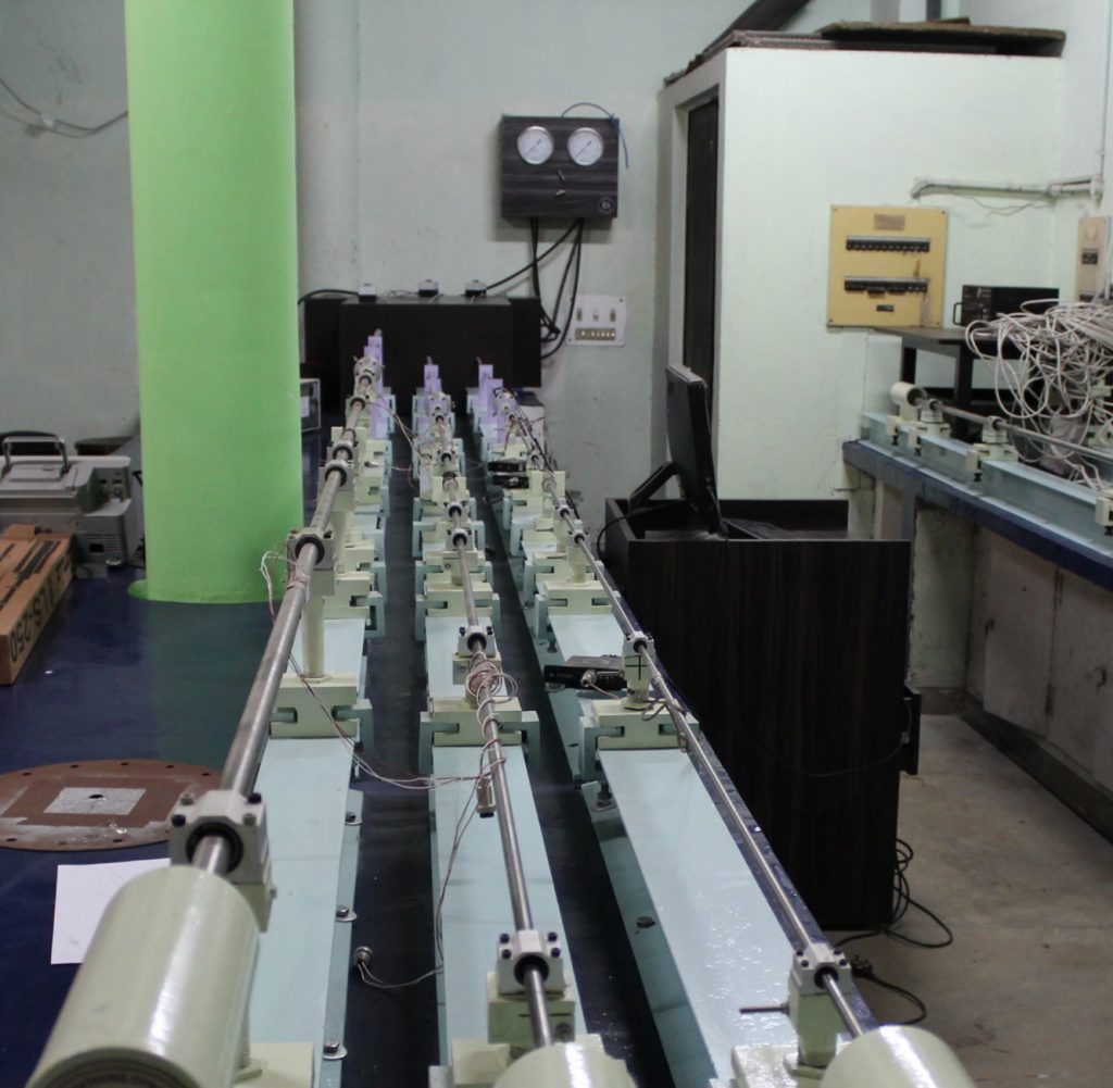
The Split Hopkinson Bar set up has been designed and fabricated in-house. Three brand new SHPB set up of differ diameters (20mm, 12mm, 8mm) are fabricated. The striker velocity can be easily controlled by varying the pressure of the compressed air in the cylinder. The driver section of the Split Hopkinson bar is a 2 ft. (610 mm) long stainless-steel pipe of wall thickness 10 mm and a nominal internal diameter of 150 mm. The barrel is a stainless steel pipe of length 2200 mm, nominal internal diameter 21 mm and outer diameter 23 mm. The picture of the experimental setup is shown in figure 5.1. The barrel length is chosen such that the effect of friction and gas dynamics in front of the projectile does not play a significant part in reducing the projectile velocity. Holes are drilled at the end of the barrel so that the projectile leaves the barrel at uniform velocity. The striker, incident and transmission bars were made of Ti-6Al-4V of 20 mm diameter. Two diametrically opposite strain gauges were mounted in a half bridge at two positions (quarter and mid-length) on incident bar and at the mid-length of the transmission bar.
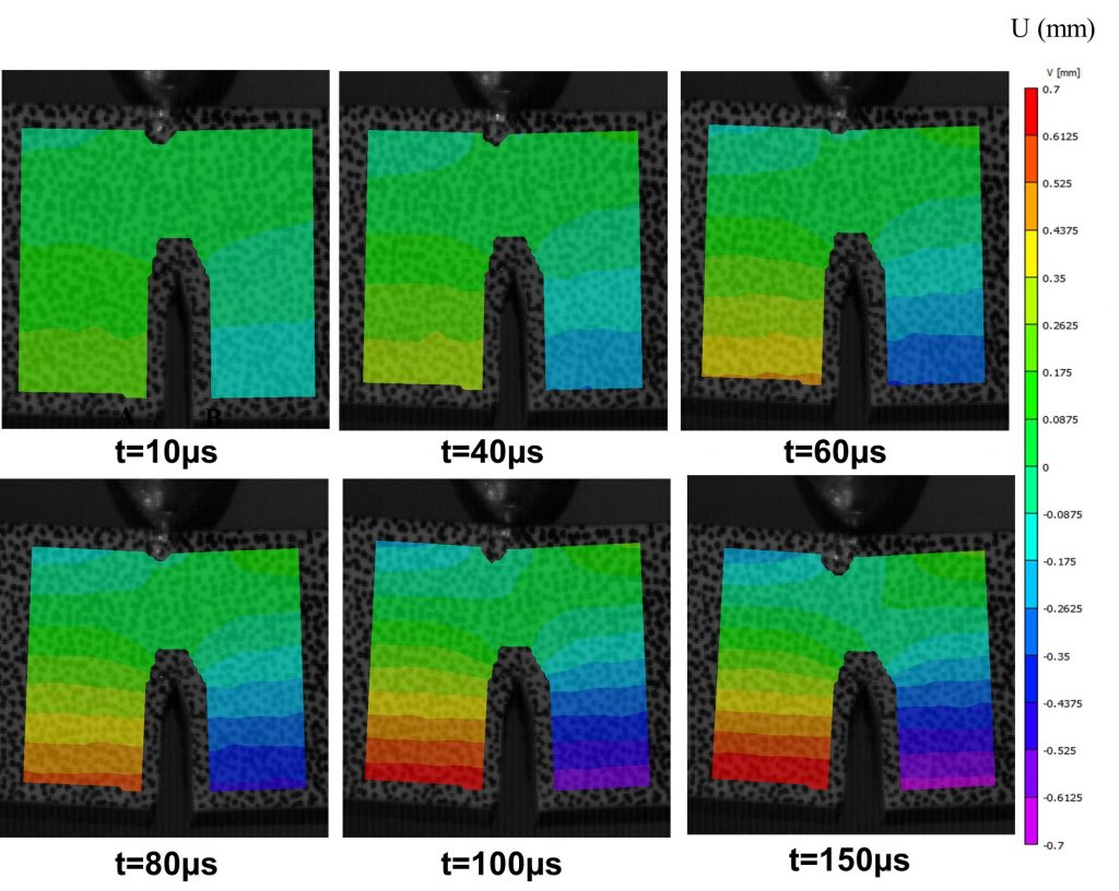
3D DIC (Digital Image Correlation)
Several experimental methods are currently available that utilize the light intensity to measure the in-plane and out-of-plane displacements. The absence of the optical components like prisms, beam splitters, spatial filter etc. and the factor that ordinary incoherent light is sufficient, makes the Digital Image Correlation technique a less demanding one. This method requires at least one high-resolution digital camera. The image is downloaded from the camera to a card where they are digitized. The specimen to be tested is covered with a random speckle pattern, whose images are captured before, during and after the deformation. The digitized images intensity measurements at each pixel location.